Solidworks Simulation Results Section View
Solid-type elements in this case are tetrahedrons that generate in place of all modeled. SOLIDWORKS Connected Help Print Feedback on this topic.

Solidworks Simulation Step Up Series Viewing Results Part 1 Youtube
You can view the full range of results including intermediate points using the Report Options described below.

Solidworks simulation results section view. After viewing the results of a static simulation Von Mises stresses and deflection in a cylindrical vessel with blind flanges at either end I would like to see a section view to see the meshing and stresses inside the vessel and between flanges. SOLIDWORKS Simulation Standard even allows me to see internal stress like the preloaded bolt pressure cone by applying a section view to the stress. This leads to plots like the one shown below.
You can also define other plots by right-clicking a result folder and selecting Define. At the very bottom of this tab is the Report section 2. When defining plots you can use reference coordinate systems.
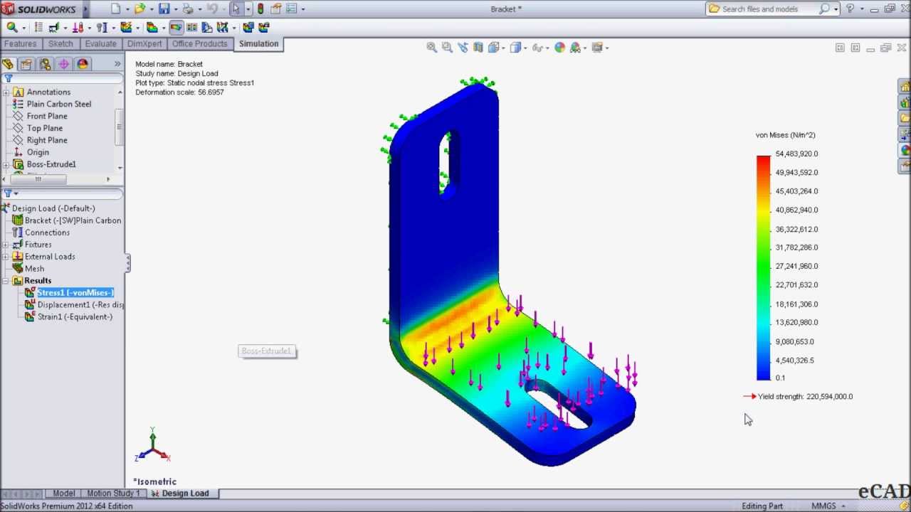
Click on this section and put all of your. Here is the circular beam part after solution with the deflection in the X-direction plotted. If this is possible could someone please give me a.
Ideally I would like to be able to do something similar to a section view to hide some of the part in order to see inside however I still want the effects that the hidden portions would produce to be included in the study. Beam-type elements are defined by a single line representing the path of a beam with the cross-sectional moment of inertia applied only as a theoretical calculation along that path. Simulation Viewing Analysis Results Processing Result Plots Creating Section Plots.
Lets take a look at the process. Viewing Analysis Results. Is this possible with a static simulation.
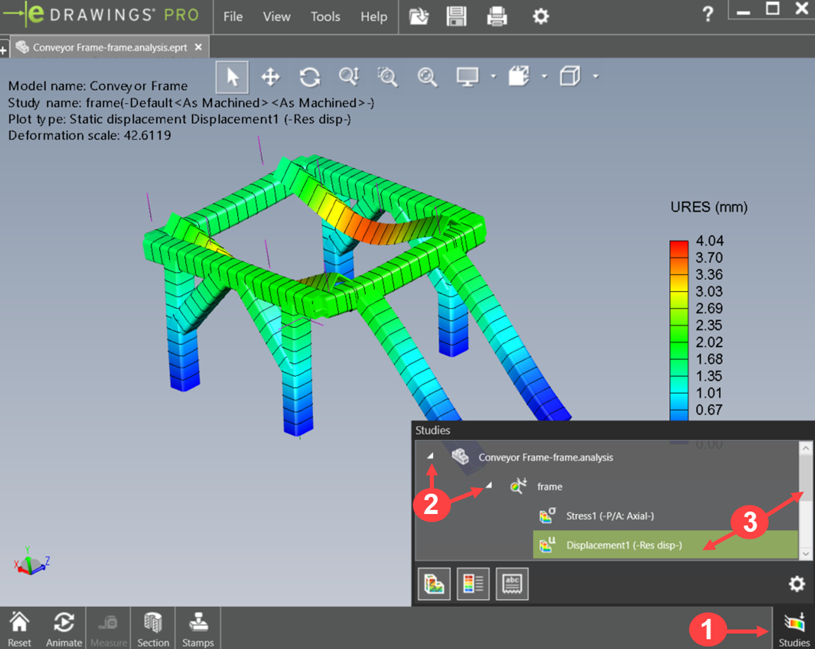
This method can be tedious but effective. In Figure 1 we have an assembly that has all its parts. However while viewing the analysis results the section view tab is selected but no section appears.
Example of the default Isometric view generated in. Minmax stress in KSI on the tank of the water tower. Viewing the displacement plot we can see there is a bending moment caused by my weight on the outside of the pull-up bar.
The result viewing tips you have seen in this blog only represent a. After experimenting a little I could not find a way. Im rather new to solidworks and simulation.
Certain tools and display settings available within SOLIDWORKS Simulation result plots can help you during the simulation result interpretation process. An important aspect of any simulation is to understand the performance of your product in terms of visual feedback as well as engineering data to back up the. In any simulation project setting up the correct boundary condition and interpreting the results are the most challenging phases regardless of the simulation software being used.
Wondering if there is a way to show a cross section of my SimulationXpress Analysis Wizard results. The Section PropertyManager appears. In SOLIDWORKS simulation we have the option to view the stress results on only specific faces andor bodies.
Simulation with SOLIDWORKS Connected. SOLIDWORKS Simulation Standard also gives granular detail to view results. There will be a point when you have a cluttered assembly and viewing your SOLIDWORKS simulation results can be difficult.
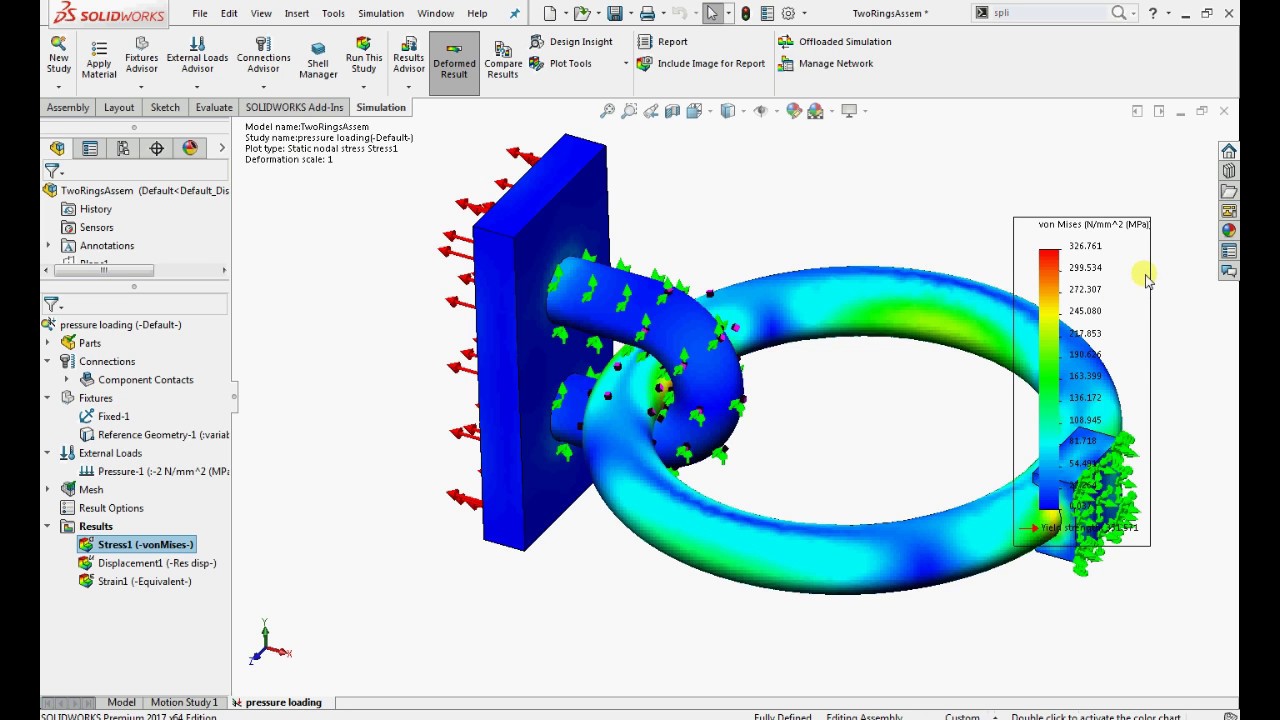
After running an analysis we can certainly visualize the results on the entire assembly but what if we wanted to localize those results on a single component for reporting purposes. When using the mesh sectioning tool its very similar to a section view but the mesh is clipped to element faces nearest the section plane. The part can simply be opened and solved in SOLIDWORKS Simulation to show the results.
Under Section 1 click Plane Cylinder or Sphere. This case study compares SOLIDWORKS Simulation results on a model as analyzed by beam and solid element types. Recently I have been asked on a couple of occasions how to isolate the Simulation results in an assembly.
In the past I have resorted to hiding and showing certain parts just to get a good view of the stress or displacement results. In the Simulation study tree right-click the active plot icon and select Section Clipping or click Plot Tools Simulation CommandManager and select Section Clipping. You can view a plot by double-clicking its icon in the Simulation study tree.
SOLIDWORKS Simulation Report Generation Tips. The default isometric view or add your own views for all of your Simulation Results data. The first thing people try to use is the Isolate command.
MySolidWorks Subscription Services Simulation Viewing Analysis Results Processing Result Plots Creating Section Plots Displaying Section Plots in Transparent Colors. And we also have the option to change the scale to match the min and max stress on just the selected entities. Simulation reports the stress tensor of six components based on the local coordinate system defined by the Stress Classification Line SCL.
So if your need is for documented verification of Simulation results check out the Verification Problems and NAFEMS Benchmarks to see if there is a theoretical. Show Mesh on Section Plane in SOLIDWORKS Simulation 2016. After running the analysis the software generates customizable default result plots.
By Javelin Technologies February 11 2016. The problem is that once you isolate the. To create a section view of the active plot.

Section Clipping In Solidworks Simulation April 2015 Youtube

Fem Simulation Results In Solidworks A After The Circular Extrude Download Scientific Diagram

Solidworks Simulation Tutorial Static Simulation Study Youtube

Solidworks Simulation Professional Buckling Analysis Youtube
Results Comparison With Solidworks Simulation Configurations

Simulation Results Don T Change When I Change Values Solidworks

Solidworks Simulation Showing Rod Displacement Of 6 In Download Scientific Diagram
Solidworks Simulation Results Export Options Goengineer

Solidworks Simulation Results Showing The Stress Left And Strain Download Scientific Diagram
Results Obtained By The Solidworks Simulation Showing The Crystallized Download Scientific Diagram
Setting Up Running A Solidworks Simulation Study Youtube
Solidworks Simulation Using Specific Displacement In Design


Layout Of Solidworks Simulation 6 Download Scientific Diagram

Solidworks Simulation Cleaning Utility
Solidworks Simulation Static Analysis With No Penetration Contact Youtube

Solidworks Simulation Maximum Annotation In Probe Tool

Solidworks 2015 Sneak Peek Incremental Simulation Results Solidworks Simulation Software
Solidworks Simulation Which Package Is Right For Me

Mesh Refinements For Accurate Results Using Solidworks Simulation Youtube
Post a Comment for "Solidworks Simulation Results Section View"